

I’m continuing my series of articles that describe how to configure various ham radio software applications to work with the Yaesu FTDX101D. All of the things I’m describing here are available on various sites and videos around the Internet, but I wanted to show what I did to make it work because it’s a real world example that might just help someone else going through the same process. As I’ve said in previous articles, even though this is written for the Yaesu FTDX101D, the same information most likely will work on any modern Yaesu radio and, with a few changes, should work on non-Yaesu radios as well.
If you haven’t done so yet, you should read my previous article, ‘Installing and Configuring Device Drivers for the Yaesu FTDX101D’ since you will need to have completed that installation before any of the following will work.
I’m also assuming that you’ve already downloaded and installed the N3FJP logger on your computer and are ready to go.
This first section is performed to allow you to connect to the advanced COM port which is used to perform rig control. This allows you to control the frequency of the radio, change modes, etc.
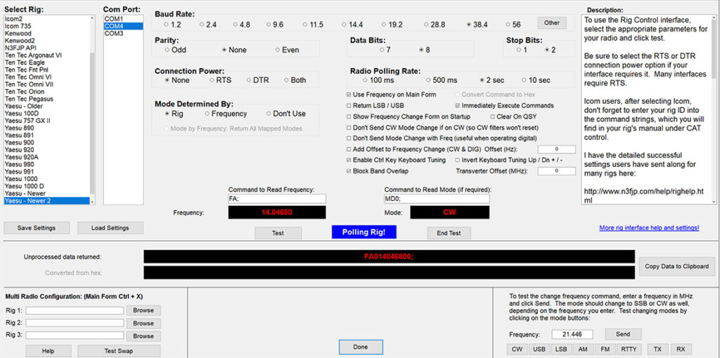
- Launch N3FJP logger and go to ‘Settings’ > ‘Rig Interface…’.
- You will now enter configuration information that matches the values that you used when installing the Yaesu device drivers. See the previous article that I mentioned above for more info.
- Enter the following information in the appropriate sections:
- ‘Select Rig’ – ‘Yaesu Newer 2’
- ‘Com Port’ – the COM port associated with your advanced COM port. In my case it was ‘COM4’.
- ‘Baud Rate’ – ‘38.4’
- ‘Parity’ – ‘None’
- ‘Data Bits’ – ‘8’
- ‘Stop Bits’ – ‘2’
- ‘Connection Power’ – ‘None’
- ‘Radio Polling Rate’ – ‘2 sec’
- ‘Mode Determined by’ – ‘Rig’
- Make sure that the following items are checked:
- ‘Use Frequency on Main Form’
- ‘Immediately Execute Commands’
- ‘Enable Ctrl Key Keyboard Tuning’
- ‘Block Band Overlap’
- Set the following text into the associated text boxes:
- ‘Command to Read Frequency’ – ‘FA;’
- ‘Command to Read Mode’ – ‘MD0;’
- After entering the above information, press the ‘Test’ button to start polling the rig. You should see the frequency and mode updating every two seconds which means you are receiving data from the rig.
- Next, test the ability to control the rig by setting a frequency in the bottom right corner of the screen and pressing the ‘Send’ button. Your rig should jump to that frequency. You can also press one of the mode keys to verify that the rig will change modes properly.
- Press ‘Done’ to dismiss the dialog.
This next section is performed to allow you to connect to the standard COM port which is used to key the transmitter.
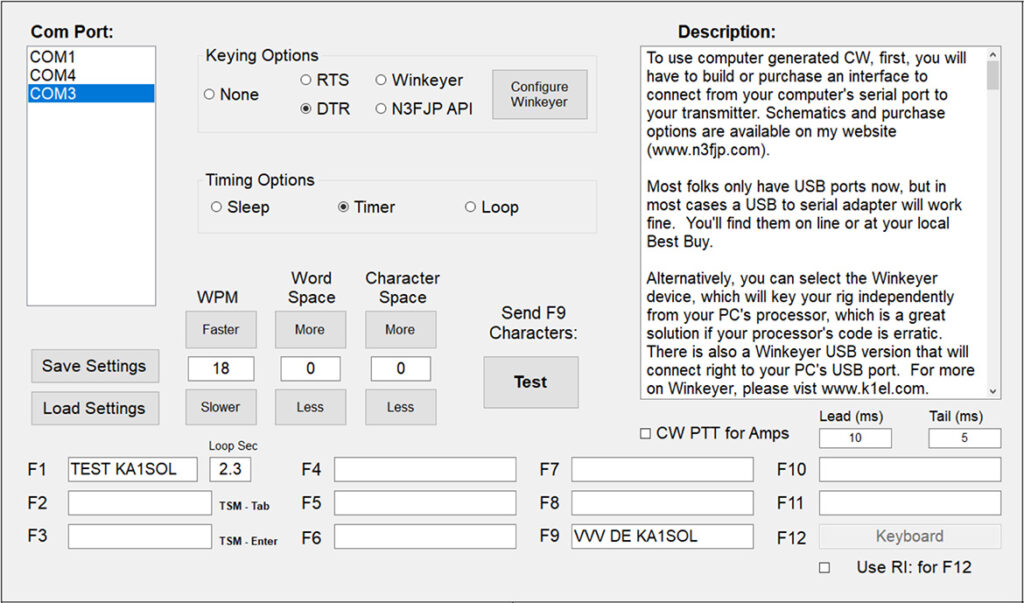
- Go to ‘Settings’ > ‘Transmit’ > ‘CW Setup’ and set the following:
- ‘Com Port’ – the COM port associated with your standard COM port. In my case it was ‘COM3’.
- ‘Keying Options’ – ‘DTR’
- To test the setup, press the ‘Test’ button which will start transmitting the text contained in the F9 box. To abort the test, press .
- If this worked, press ‘Done’ to dismiss the dialog and you are ready to go. If not, you’ll have some troubleshooting to do. If you’re having a keying problem, verify that the COM3 settings you entered here, match those you did during the standard driver installation. If you’re having a rig control problem, verify that the COM4 settings you entered here, match those you did during the standard driver installation.
That’s it. It’s not really all that bad. The thing to remember is that you can uses many different combinations of device settings to control your rig but in order for them to work, both your software and your drivers must use the same settings. The settings I’ve used above have been tested and are known to work so I encourage you to use the same values.